piping isometric drawing symbols
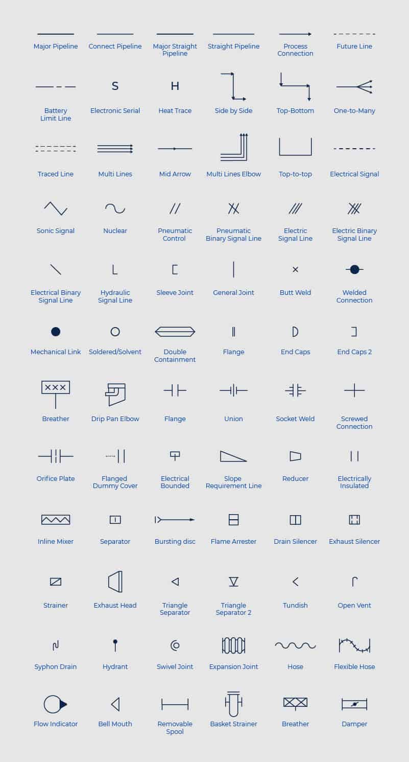
Is called as Piping and Instrumentation Drawing is a pictorial representation of Pipeline in a single line diagram along with processing. Symbols are shown in black lines.

Piping Design Basics Isometric Drawings What Is Piping
Plumbing and Piping Plans solution extends ConceptDraw PRO v1022 software with samples templates and libraries of pipes plumbing and valves design elements for developing of water.

. Up to 10 cash back Learn how to READ INTERPRET and successfully UNDERSTAND ALL Piping Isometrics through numerous real industrial examples. This video depicts isometric drawing symbols for piping special items such as strainers flow sight glass drip rings etcFor info check out this page. In CAD drawing only x and y co-ordinates are.
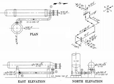
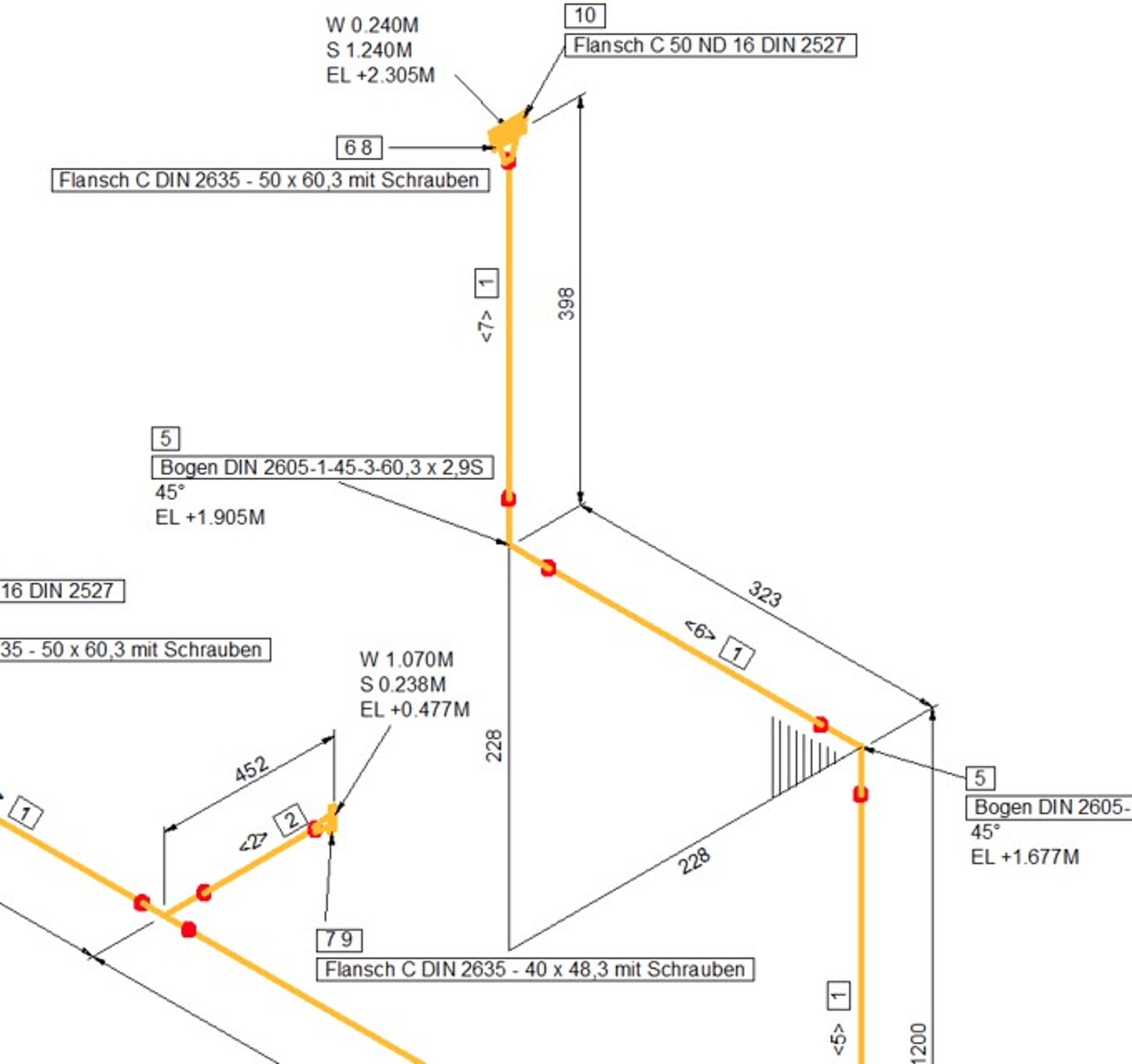
Lighter lines show connected pipe and are not parts. Basic Piping Isometric Drawings Piping Analysis A piping isometric drawing is a 2D drawing in which piping is represented like a 3D drawing. Isometric symbols for fittings flanges and valves represent all sizes of pipe.
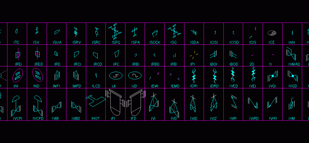
Various symbols are used to indicate piping components instrumentation equipments in engineering drawings such as Piping and Instrumentation Diagram PID Isometric Drawings. The fitting flange and valve drawing symbols unique to isometrics are depicted. 12 Inch 34 Inch 1 Inch 15 Inch 2 Inch 3 Inch 4 Inch 6 Inch 8 Inch 10 Inch 12 Inch 14 Inch 16 Inch 18 Inch 20 Inch 24 Inch 26 Inch 28 Inch 30.
Isometric Drawing Piping Download Free. Example of Pipe Isometric Drawing. Piping Isometric Drawing Symbols Pdf at GetDrawings Free from Select from a dialog box choose a symbol and the view you need.
12 Inch 34 Inch 1 Inch 15 Inch 2 Inch 3 Inch 4 Inch 6 Inch 8 Inch 10 Inch 12 Inch 14 Inch 16 Inch 18 Inch 20 Inch 24 Inch 26 Inch 28 Inch 30. The use of a North Arrow in establishing pipe orientation and routing on the isometric is shown graphically. P ID.
As i mentioned in part 2 the meanings of. No attempt is made to represent a pipes actual size or pound rating graphically. Identify the 5 key sections of.
Piping Spacing Calculator Details for Pipe 1 NPD. Piping Spacing Calculator Details for Pipe 1 NPD. Piping Coordination System - Mechanical symbols for Isometric drawings Isometrics Symbols Note.
Piping Coordination Systems - Mechanical symbols for Isometric drawings Image Fittings Butt weld Symbol Socket Weld Symbol Threaded Symbol Fittings Image. Block Library CAD CAD Symbol Tag.

Isometric Pipe Drawing Download

Piping Coordination Systems Mechanical Symbols For Isometric Drawings Pdf Pdf Pipe Fluid Conveyance Chemical Engineering
Go 3d With Free Isometric Piping Shapes For Visio Visio Guy

Blocks Pipes Dwg Block For Autocad Designs Cad

Isometric Pipe Drawing Download

Isometric Drawing Symbol Fitterkipurijankari

How To Change The Support Symbol For Generated Isometric Drawing Openplant Autoplant Wiki Openplant Autoplant Bentley Communities

Isometric Piping Accesories Symbols Dwg Drawing Free In Cad

Isometric Piping Symbols For Autocad And Lt

Isometric Drawing Symbols For Piping Fittings The Piping Engineering World
P Id Piping Instrumentation Diagram Valve Symbols Sio

Piping Isometrics 2021 Vertex G4plant 2021 Documentation

Piping Design Basics Isometric Drawings What Is Piping

Piping Isometrics Demystified Through Practical Examples

Pipe Fittings Infographic Graphic Products


